Wednesday, February 17, 2016

FUSE

Fuse Introduction: A fuse is a short piece of metal , inserted in the circuit, Which melts when excessive current flows through it and thus breaks the circuit .

How it work
 The fuse element is generally made of materials having low melting point ,high conductivity and least deterioration due to oxidation eg., silver, copper etc. It is inserted in series with the circuit to be protected . Under normal operating conditions , the fuse element is at a temperature below its melting point . Therefore , it carries the normal current without overheating . However , When a short-circuit or overload occurs, the current through the fuse increases beyond its rated value. This raises the temperature and fuse element melts (or blows out), disconnecting the circuit protected by it. In this way , a fuse protects the machines and equipment from damage due to excessive currents.


Electrical fuse 

Monday, February 15, 2016

Resistor

Resistor : It is one kind of power which prevents the flow of current.
A resistor is one of the most fundamental components in electronics. Its purpose is to impede a flow of current and impose a voltage reduction. It consists of two wires or conductors attached at opposite ends or sides of a relatively poor electrical conductor, the resistance of which is measured in ohms, universally represented by the Greek omega symbol, Ω.


Example: The electronic component known as the resistor is best described as electrical friction. Pretend, for a moment, that electricity travels through hollow pipes like water. Assume two pipes are filled with water and one pipe has very rough walls. It would be easy to say that it is more difficult to push the water through the rough-walled pipe than through a pipe with smooth walls. The pipe with rough walls could be described as having more resistance to movement than the smooth one.

Electronic resistor .


How It Works
In the process of impeding the flow of current and reducing voltage, a resistor absorbs electrical energy, which it must dissipate as heat. In most modern electronic circuits, the heat dissipation is typically a fraction of a watt. If R is the resistance in ohms, I is the current flowing through the resistor in amperes, and V is the voltage drop imposed by the resistor (the difference in electrical potential between the two contacts that are attached to it), Ohm’s law states:
V = I / R
This is another way of saying that a resistor of 1Ω will allow a current of 1 amp when the potential difference between the ends of the resistor is 1 volt. If W is the power in watts dissipated by the resistor, in a DC circuit:
W = V * I
By substitution in Ohm’s law, we can express watts in terms of current and resistance:
W = I2 / R

We can also express watts in terms of voltage and resistance:
W = V2 * R

These alternates may be useful in situations where you do not know the voltage drop or the current, respectively. Approximately similar relationships exist when using alternating current, although the power will be a more complex function.

Values
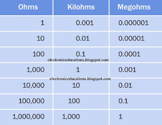
1 kilohm, usually written as 1K, is 1,000Ω. 1 megohm, usually written as 1M or 1 meg, is 1,000K. 1 gigaohm is 1,000 megs, although the unit is rarely used. Resistances of less than 1Ω are uncommon and are usually expressed as a decimal number followed by the Ω symbol. The term milliohms (thousandths of an ohm) is used in special applications. Equivalent resistor values are shown in picture .


Tolerance
The tolerance, or precision, of a resistor may range from plus-or-minus 0.001% up to plus-orminus 20%, but is most commonly plus-or-minus 1%, 2%, 5%, or 10%.


Saturday, February 13, 2016

FM Transmitter Circuit Diagram.


FM TRANSMITTER: Fm transmitter is very easy project. FM transmitter Meaning frequency modulation transmitter .It has a range of up to 300 meter.

Fm transmitter is main problem is Modulation coil. Now we make its very easy.
L1 is our coil its need 8 to 10 turns of 22 gauge hookup wire. Any kinds of ¼ inch diameter round pen or pencil.

C4 is a trimmer capacitor 4-40pF.

Must we use DC battery for good work.

So we make the circuit as our diagram.

Every man make fm transmitter it’s not work its need good adjustment. When we make the circuit then on our fm radio that position whis position no any other channel signal ,Now we adjust our C4 capacitor when we get our own signal when stop our adjusting work .

Coming soon 2k FM Transmitter circuit diagram.


Thursday, February 11, 2016

Microphone circuit diagram

 Microphone : Microphone is a input device its input sound and convert electrical signal .


This is Microphone


Now we make a Microphone .
If you make microphone its main problem is noise . we need a noise free microphone so need 3 volt DC power supply must be use battery .
Its very simple and low cost circuit .Only three resistance two capacitor one transistor and one mic .


Microphone Circuit Diagram 
               

Wednesday, February 10, 2016

Sound Amplifier


Sound Amplifier 

 We need good quality sound system .
LA 4422 IC its a good quality sound system and very low cost . LA 4422 Sound quality is noise free and good base .

Its need  12 volt  power supply .
               10 watt speaker .


            IC-    LA 4422


Circuit Diagram


Tuesday, February 24, 2015

What is UPS ?

UPS : Uninterruptible power supply .

UPS 
  In general , a UPS contains a rechargeable battery and DC to AC convert circuitry . The battery charging circuitry in the UPS will maintain the battery at a full charge during normal operation . If the AC  power supply falls low or goes off for any reason , the inverter automatically turns on to maintain the 230 volt AC power supply  instantly , no any change UPS output power . Its called UPS .You can continue to work on the computer , either until the UPS battery discharges ,or until the AC power comes back . At the very least ,this will give you enough time to save files and shut down your computer system normally .

HOW TO MAKE A UPS ...........Coming soon .


UPS BLOCK DIAGRAM 


Sunday, February 22, 2015

What is inductors ?

Inductors : Basically , inductors are coils that have large inductance . They oppose the change of current flowing through them , and are used in power supplies for filtering out ripples .

Their principle of working is explained below .
 We know that  the flow of current through a conductor is accompanied by magnetic effects . The transfer of electrical energy to the magnetic field represents work done by the source of emf . power is required for doing work , and since power is equal to current multiplied by voltage ,there must be a voltage drop in the circuit during the time which energy is being stored in the field .This voltage '' drop'' (which has nothing to do with the voltage drop in any resistance in the circuit ) is the result of an opposing voltage value .When the field becomes constant the induced emf or back emf disappears,since no further energy is being stored . Since the induced emf opposes the emf of the source , it tends to prevent the current from rising rapidly when the circuits is closed .The amplitude of the induced emf is proportional to the rate at which the current is changing and to a constant associated with the circuit itself , called the inductance of the circuit .